Tuesday, 8 January 2013

concave


The method for drawing ray diagrams for concave mirror is described below. The method is applied to the task of drawing a ray diagram for an object located beyond the center of curvature (C) of a concave mirror. Yet the same method works for drawing a ray diagram for any object location.
1. Pick a point on the top of the object and draw two incident rays traveling towards the mirror.
Using a straight edge, accurately draw one ray so that it passes exactly through the focal point on the way to the mirror. Draw the second ray such that it travels exactly parallel to the principal axis. Place arrowheads upon the rays to indicate their direction of travel.
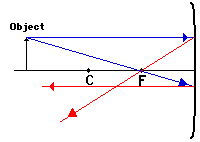

2. Once these incident rays strike the mirror, reflect them according to the two rules of reflection for concave mirrors.
The ray that passes through the focal point on the way to the mirror will reflect and travel parallel to the principal axis. Use a straight edge to accurately draw its path. The ray that traveled parallel to the principal axis on the way to the mirror will reflect and travel through the focal point. Place arrowheads upon the rays to indicate their direction of travel. Extend the rays past their point of intersection.
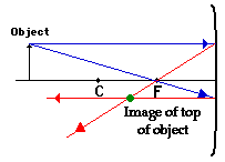
3. Mark the image of the top of the object.
The image point of the top of the object is the point where the two reflected rays intersect. If your were to draw a third pair of incident and reflected rays, then the third reflected ray would also pass through this point. This is merely the point where all light from the top of the object would intersect upon reflecting off the mirror. Of course, the rest of the object has an image as well and it can be found by applying the same three steps to another chosen point. (See note below.)
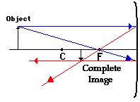

4. Repeat the process for the bottom of the object.
The goal of a ray diagram is to determine the location, size, orientation, and type of image that is formed by the concave mirror. Typically, this requires determining where the image of the upper and lower extreme of the object is located and then tracing the entire image. After completing the first three steps, only the image location of the top extreme of the object has been found. Thus, the process must be repeated for the point on the bottom of the object. If the bottom of the object lies upon the principal axis (as it does in this example), then the image of this point will also lie upon the principal axis and be the same distance from the mirror as the image of the top of the object. At this point the entire image can be filled in.


Some students have difficulty understanding how the entire image of an object can be deduced once a single point on the image has been determined. If the object is a vertically aligned object (such as the arrow object used in the example below), then the process is easy. The image is merely a vertical line. In theory, it would be necessary to pick each point on the object and draw a separate ray diagram to determine the location of the image of that point. That would require a lot of ray diagrams as illustrated below.
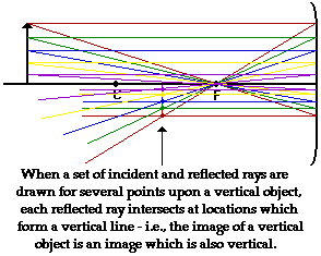
Fortunately, a shortcut exists. If the object is a vertical line, then the image is also a vertical line. For our purposes, we will only deal with the simpler situations in which the object is a vertical line that has its bottom located upon the principal axis. For such simplified situations, the image is a vertical line with the lower extremity located upon the principal axis.
The ray diagram above illustrates that when the object is located at a position beyond the center of curvature, the image is located at a position between the center of curvature and the focal point. Furthermore, the image is inverted, reduced in size (smaller than the object), and real. This is the type of information that we wish to obtain from a ray diagram. These characteristics of the image will be discussed in more detail in the next section of Lesson 3.
Once the method of drawing ray diagrams is practiced a couple of times, it becomes as natural as breathing. Each diagram yields specific information about the image. The two diagrams below show how to determine image location, size, orientation and type for situations in which the object is located at the center of curvature and when the object is located between the center of curvature and the focal point.
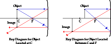
It should be noted that the process of constructing a ray diagram is the same regardless of where the object is located. While the result of the ray diagram (image location, size, orientation, and type) is different, the same two rays are always drawn. The two rules of reflection are applied in order to determine the location where all reflected rays appear to diverge from (which for real images, is also the location where the reflected rays intersect).
In the three cases described above - the case of the object being located beyond C, the case of the object being located at C, and the case of the object being located between C and F - light rays are converging to a point after reflecting off the mirror. In such cases, a real image is formed. As discussed previously, a real image is formed whenever reflected light passes through the image location. While plane mirrors always produce virtual images, concave mirrors are capable of producing both real and virtual images. As shown above, real images are produced when the object is located a distance greater than one focal length from the mirror. A virtual image is formed if the object is located less than one focal length from the concave mirror. To see why this is so, a ray diagram can be used.
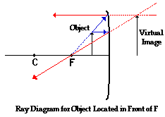


Ray Diagram for the Formation of a Virtual Image
A ray diagram for the case in which the object is located in front of the focal point is shown in the diagram at the right. Observe that in this case the light rays diverge after reflecting off the mirror. When light rays diverge after reflection, a virtual image is formed. As was done with plane mirrors, the image location can be found by tracing all reflected rays backwards until they intersect. For every observer, the reflected rays would seem to be diverging from this point. Thus, the point of intersection of the extended reflected rays is the image point. Since light does not actually pass through this point (light never travels behind the mirror), the image is referred to as a virtual image. Observe that when the object in located in front of the focal point, its image is an upright and enlarged image that is located on the other side of the mirror. In fact, one generalization that can be made about all virtual images produced by mirrors (both plane and curved) is that they are always upright and always located on the other side of the mirror.


Ray Diagram for an Object Located at the Focal Point
Thus far we have seen via ray diagrams that a real image is produced when an object is located more than one focal length from a concave mirror; and a virtual image is formed when an object is located less than one focal length from a concave mirror (i.e., in front of F). But what happens when the object is located at F? That is, what type of image is formed when the object is located exactly one focal length from a concave mirror? Of course a ray diagram is always one tool to help find the answer to such a question. However, when a ray diagram is used for this case, an immediate difficulty is encountered. The incident ray that begins from the top extremity of the object and passes through the focal point does not meet the mirror. Thus, a different incident ray must be used in order to determine the intersection point of all reflected rays. Any incident light ray would work as long as it meets up with the mirror. Recall that the only reason that we have used the two we have is that they can be conveniently and easily drawn. The diagram below shows two incident rays and their corresponding reflected rays.
For the case of the object located at the focal point (F), the light rays neither converge nor diverge after reflecting off the mirror. As shown in the diagram above, the reflected rays are traveling parallel to each other. Subsequently, the light rays will not converge on the object's side of the mirror to form a real image; nor can they be extended backwards on the opposite side of the mirror to intersect to form a virtual image. So how should the results of the ray diagram be interpreted? The answer: there is no image!! Surprisingly, when the object is located at the focal point, there is no location in space at which an observer can sight from which all the reflected rays appear to be diverging. An image is not formed when the object is located at the focal point of a concave mirror.

Monday, 7 January 2013

diverging lens


Step-by-Step Method for Drawing Ray Diagrams
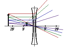
The method of drawing ray diagrams for a double concave lens is described below.
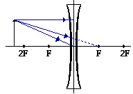
1. Pick a point on the top of the object and draw three incident rays traveling towards the lens.
Using a straight edge, accurately draw one ray so that it travels towards the focal point on the opposite side of the lens; this ray will strike the lens before reaching the focal point; stop the ray at the point of incidence with the lens. Draw the second ray such that it travels exactly parallel to the principal axis. Draw the third ray to the exact center of the lens. Place arrowheads upon the rays to indicate their direction of travel.
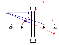

2. Once these incident rays strike the lens, refract them according to the three rules of refraction for double concave lenses.
The ray that travels towards the focal point will refract through the lens andtravel parallel to the principal axis. Use a straight edge to accurately draw its path. The ray that traveled parallel to the principal axis on the way to the lens will refract and travel in a direction such that its extension passes through the focal point on the object's side of the lens. Align a straight edge with the point of incidence and the focal point, and draw the second refracted ray. The ray that traveled to the exact center of the lens will continue to travel in the same direction. Place arrowheads upon the rays to indicate their direction of travel. The three rays should be diverging upon refraction.
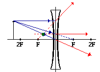

3. Locate and mark the image of the top of the object.
The image point of the top of the object is the point where the three refracted rays intersect. Since the three refracted rays are diverging, they must be extended behind the lens in order to intersect. Using a straight edge, extend each of the rays using dashed lines. Draw the extensions until they intersect. All three extensions should intersect at the same location. The point of intersection is the image point of the top of the object. The three refracted rays would appear to diverge from this point. This is merely the point where all light from the top of the object would appear to diverge from after refracting through the double concavelens. Of course, the rest of the object has an image as well and it can be found by applying the same three steps to another chosen point. See note below.
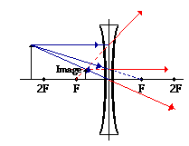

4. Repeat the process for the bottom of the object.
The goal of a ray diagram is to determine the location, size, orientation, and type of image that is formed by the double concave lens. Typically, this requires determining where the image of the upper and lower extreme of the object is located and then tracing the entire image. After completing the first three steps, only the image location of the top extreme of the object has been found. Thus, the process must be repeated for the point on the bottom of the object. If the bottom of the object lies upon the principal axis (as it does in this example), then the image of this point will also lie upon the principal axis and be the same distance from the lens as the image of the top of the object. At this point the complete image can be filled in.

Some students have difficulty understanding how the entire image of an object can be deduced once a single point on the image has been determined. If the object is merely a vertical object (such as the arrow object used in the example below), then the process is easy. The image is merely a vertical line. This is illustrated in the diagram below. In theory, it would be necessary to pick each point on the object and draw a separate ray diagram to determine the location of the image of that point. That would require a lot of ray diagrams as illustrated in the diagram below.
Fortunately, a shortcut exists. If the object is a vertical line, then the image is also a vertical line. For our purposes, we will only deal with the simpler situations in which the object is a vertical line that has its bottom located upon the principal axis. For such simplified situations, the image is a vertical line with the lower extremity located upon the principal axis.
The ray diagram above illustrates that the image of an object in front of a double concave lens will be located at a position behind the double concave lens. Furthermore, the image will be upright, reduced in size (smaller than the object), and virtual. This is the type of information that we wish to obtain from a ray diagram. The characteristics of this image will be discussed in more detail in the next section of Lesson 5.

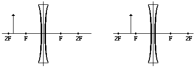
Once the method of drawing ray diagrams is practiced a couple of times, it becomes as natural as breathing. Each diagram yields specific information about the image. It is suggested that you take a few moments to practice a few ray diagrams on your own and to describe the characteristics of the resulting image. The diagrams below provide the setup; you must merely draw the rays and identify the image. If necessary, refer to the method described above.


convex mirror


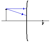
e method of drawing ray diagrams for convex mirrors is described below.
1. Pick a point on the top of the object and draw two incident rays traveling towards the mirror.
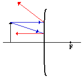
Using a straight edge, accurately draw one ray so that it travels towards the focal point on the opposite side of the mirror; this ray will strike the mirror before reaching the focal point; stop the ray at the point of incidence with the mirror. Draw the second ray such that it travels exactly parallel to the principal axis. Place arrowheads upon the rays to indicate their direction of travel.


2. Once these incident rays strike the mirror, reflect them according to the two rules of reflection for convex mirrors.
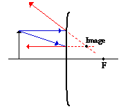
The ray that travels towards the focal point will reflect and travel parallel to the principal axis. Use a straight edge to accurately draw its path. The ray that traveled parallel to the principal axis on the way to the mirror will reflect and travel in a direction such that its extension passes through the focal point. Align a straight edge with the point of incidence and the focal point, and draw the second reflected ray. Place arrowheads upon the rays to indicate their direction of travel. The two rays should be diverging upon reflection.


3. Locate and mark the image of the top of the object.
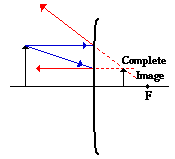
The image point of the top of the object is the point where the two reflected rays intersect. Since the two reflected rays are diverging, they must be extended behind the mirror in order to intersect. Using a straight edge, extend each of the rays using dashed lines. Draw the extensions until they intersect. The point of intersection is the image point of the top of the object. Both reflected rays would appear to diverge from this point. If your were to draw a third pair of incident and reflected rays, then the extensions of the third reflected ray would also pass through this point. This is merely the point where all light from the top of the object would appear to diverge from upon reflecting off the mirror. Of course, the rest of the object has an image as well and it can be found by applying the same three steps for another chosen point. See note below.


4. Repeat the process for the bottom of the object.
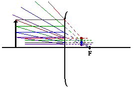
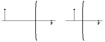
The goal of a ray diagram is to determine the location, size, orientation, and type of image that is formed by the convex mirror. Typically, this requires determining where the image of the upper and lower extreme of the object is located and then tracing the entire image. After completing the first three steps, only the image location of the top extreme of the object has been found. Thus, the process must be repeated for the point on the bottom of the object. If the bottom of the object lies upon the principal axis (as it does in this example), then the image of this point will also lie upon the principal axis and be the same distance from the mirror as the image of the top of the object. At this point the complete image can be filled in.

  1.  
Some students have difficulty understanding how the entire image of an object can be deduced once a single point on the image has been determined. If the object is merely a vertical object (such as the arrow object used in the example below), then the process is easy. The image is merely a vertical line. This is illustrated in the diagram below. In theory, it would be necessary to pick each point on the object and draw a separate ray diagram to determine the location of the image of that point. That would require a lot of ray diagrams as illustrated in the diagram below.
Fortunately, a shortcut exists. If the object is a vertical line, then the image is also a vertical line. For our purposes, we will only deal with the simpler situations in which the object is a vertical line that has its bottom located upon the principal axis. For such simplified situations, the image is a vertical line with the lower extremity located upon the principal axis.
The ray diagram above illustrates that the image of an object in front of a convex mirror will be located at a position behind the convex mirror. Furthermore, the image will be upright, reduced in size (smaller than the object), and virtual. This is the type of information that we wish to obtain from a ray diagram. The characteristics of this image will be discussed in more detail in the next section of Lesson 4.
Once the method of drawing ray diagrams is practiced a couple of times, it becomes as natural as breathing. Each diagram yields specific information about the image. It is suggested that you take a few moments to practice a few ray diagrams on your own and to describe the characteristics of the resulting image. The diagrams below provide the setup; you must merely draw the rays and identify the image. If necessary, refer to the method described above.


physics convirging lens


 converging lens :

Case 1: The object is located beyond 2F

When the object is located at a location beyond the 2F point, the image will always be located somewhere in between the 2F point and the focal point (F) on the other side of the lens. Regardless of exactly where the object is located, the image will be located in this specified region. In this case, the image will be an inverted image. That is to say, if the object is right side up, then the image is upside down. In this case, the image isreduced in size; in other words, the image dimensions are smaller than the object dimensions. If the object is a six-foot tall person, then the image is less than six feet tall. Earlier in Unit 13, the termmagnification was introduced; the magnification is the ratio of the height of the object to the height of the image. In this case, the magnification is a number with an absolute value less than 1. Finally, the image is a real image. Light rays actually converge at the image location. If a sheet of paper were placed at the image location, the actual replica or likeness of the object would appear projected upon the sheet of paper.

Case 2: The object is located at 2F

When the object is located at the 2F point, the image will also be located at the 2F point on the other side of the lens. In this case, the image will be inverted (i.e., a right side up object results in an upside-down image). The image dimensions are equal to the object dimensions. A six-foot tall person would have an image that is six feet tall; the absolute value of the magnification is exactly 1. Finally, the image is a real image. Light rays actually converge at the image location. As such, the image of the object could be projected upon a sheet of paper.

Case 3: The object is located between 2F and F

When the object is located in front of the 2F point, the image will be located beyond the 2F point on the other side of the lens. Regardless of exactly where the object is located between 2F and F, the image will be located in the specified region. In this case, the image will be inverted (i.e., a right side up object results in an upside-down image). The image dimensions are larger than the object dimensions. A six-foot tall person would have an image that is larger than six feet tall. The absolute value of the magnification is greater than 1. Finally, the image is a real image. Light rays actually converge at the image location. As such, the image of the object could be projected upon a sheet of paper.

Case 4: The object is located at F

When the object is located at the focal point, no image is formed. As discussed earlier in Lesson 5, the refracted rays neither converge nor diverge. After refracting, the light rays are traveling parallel to each other and cannot produce an image.

Case 5: The object is located in front of F

When the object is located at a location in front of the focal point, the image will always be located somewhere on the same side of the lens as the object. Regardless of exactly where in front of F the object is located, the image will always be located on the object's side of the lens and somewhere further from the lens. The image is located behind the object. In this case, the image will be an upright image. That is to say, if the object is right side up, then the image will also be right side up. In this case, the image isenlarged; in other words, the image dimensions are greater than the object dimensions.A six-foot tall person would have an image that is larger than six feet tall. The magnification is greater than 1. Finally, the image is a virtual image. Light rays diverge upon refraction; for this reason, the image location can only be found by extending the refracted rays backwards on the object's side the lens. The point of their intersection is the virtual image location. It would appear to any observer as though light from the object were diverging from this location. Any attempt to project such an image upon a sheet of paper would fail since light does not actually pass through the image location.
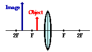
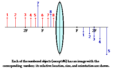
It might be noted from the above descriptions that there is a relationship between the object distance and object size and the image distance and image size. Starting from a large value, as the object distance decreases (i.e., the object is moved closer to the lens), the image distance increases; meanwhile, the image height increases. At the 2F point, the object distance equals the image distance and the object height equals the image height. As the object distance approaches one focal length, the image distance and image height approaches infinity. Finally, when the object distance is equal to exactly one focal length, there is no image. Then altering the object distance to values less than one focal length produces images that are upright, virtual and located on the same side of the lens as the object. Finally, if the object distance approaches 0, the image distance approaches 0 and the image height ultimately becomes equal to the object height. These patterns are depicted in the diagram below. Eight different object locations are drawn in red and labeled with a number; the corresponding image locations are drawn in blue and labeled with the identical number.

Friday, 14 December 2012

mayan : rise and fall


The Maya Empire, centered in the tropical lowlands of what is now Guatemala, reached the peak of its power and influence around the sixth century A.D. The Maya excelled at agriculture, pottery, hieroglyph writing, calendar-making and mathematics, and left behind an astonishing amount of impressive architecture and symbolic artwork. Most of the great stone cities of the Maya were abandoned by A.D. 900, however, and since the 19th century scholars have debated what might have caused this dramatic decline.

Locating the Maya

The Maya civilization was one of the most dominant indigenous societies of Mesoamerica (a term used to describe Mexico and Central America before the 16th century Spanish conquest). Unlike other scattered indigenous populations of Mesoamerica, the Maya were centered in one geographical block covering all of the Yucatan Peninsula and modern-day Guatemala; Belize and parts of the Mexican states of Tabasco and Chiapas; and the western part of Honduras and El Salvador. This concentration showed that the Maya remained relatively secure from invasion by other Mesoamerican peoples.
Within that expanse, the Maya lived in three separate sub-areas with distinct environmental and cultural differences: the northern Maya lowlands on the Yucatan Peninsula; the southern lowlands in the Peten district of northern Guatemala and adjacent portions of Mexico, Belize and western Honduras; and the southern Maya highlands, in the mountainous region of southern Guatemala. Most famously, the Maya of the southern lowland region reached their peak during the Classic Period of Maya civilization (A.D. 250 to 900), and built the great stone cities and monuments that have fascinated explorers and scholars of the region.

Early Maya, 1800 B.C. to A.D. 250

The earliest Maya settlements date to around 1800 B.C., or the beginning of what is called the Preclassic or Formative Period. The earliest Maya were agricultural, growing crops such as corn (maize), beans, squash and cassava (manioc). During the Middle Preclassic Period, which lasted until about 300 B.C., Maya farmers began to expand their presence both in the highland and lowland regions. The Middle Preclassic Period also saw the rise of the first major Mesoamerican civilization, the Olmecs. Like other Mesamerican peoples, such as the Zapotec, Totonac, Teotihuacán and Aztec, the Maya derived a number of religious and cultural traits--as well as their number system and their famous calendar--from the Olmec.
In addition to agriculture, the Preclassic Maya also displayed more advanced cultural traits like pyramid-building, city construction and the inscribing of stone monuments.
The Late Preclassic city of Mirador, in the northern Peten, was one of the greatest cities ever built in the pre-Columbian Americas. Its size dwarfed the Classic Maya capital of Tikal, and its existence proves that the Maya flourished centuries before the Classic Period. 

Cities of Stone: The Classic Maya, A.D. 250-900

The Classic Period, which began around A.D. 250, was the golden age of the Maya Empire. Classic Maya civilization grew to some 40 cities, including Tikal, Uaxactún, Copán, Bonampak, Dos Pilas, Calakmul, Palenque and Río Bec; each city held a population of between 5,000 and 50,000 people. At its peak, the Maya population may have reached 2,000,000.  
Excavations of Maya sites have unearthed plazas, palaces, temples and pyramids, as well as courts for playing the ball games that were ritually and politically significant to Maya culture. Maya cities were surrounded and supported by a large population of farmers. Though the Maya practiced a primitive type of "slash-and-burn" agriculture, they also displayed evidence of more advanced farming methods, such as irrigation and terracing.
The Maya were deeply religious, and worshiped various gods related to nature, including the gods of the sun, the moon, rain and corn. At the top of Maya society were the kings, or "kuhul ajaw" (holy lords), who claimed to be related to gods and followed a hereditary succession. They were thought to serve as mediators between the gods and people on earth, and performed the elaborate religious ceremonies and rituals so important to the Maya culture.
The Classic Maya built many of their temples and palaces in a stepped pyramid shape, decorating them with elaborate reliefs and inscriptions. These structures have earned the Maya their reputation as the great artists of Mesoamerica. Guided by their religious ritual, the Maya also made significant advances in mathematics and astronomy, including the use of the zero and the development of a complex calendar system based on 365 days. Though early researchers concluded that the Maya were a peaceful society of priests and scribes, later evidence--including a thorough examination of the artwork and inscriptions on their temple walls--showed the less peaceful side of Maya culture, including the war between rival Mayan city-states and the importance of torture and human sacrifice to their religious ritual.
Serious exploration of Classic Maya sites began in the 1830s. By the early to mid-20th century, a small portion of their system of hieroglyph writing had been deciphered, and more about their history and culture became known. Most of what historians know about the Maya comes from what remains of their architecture and art, including stone carvings and inscriptions on their buildings and monuments. The Maya also made paper from tree bark and wrote in books made from this paper, known as codices; four of these codices are known to have survived.

Mathematics

Maya numerals
In common with the other Mesoamerican civilizations, the Maya used a base 20 (vigesimal) and base 5 numbering system (see Maya numerals). Also, the preclassic Maya and their neighbors had independently developed the concept of zero by 36 BC. Inscriptions show them on occasion working with sums up to the hundreds of millions and dates so large it would take several lines just to represent it. They produced extremely accurate astronomical observations; their charts of the movements of the moon and planets are equal or superior to those of any other civilization working from naked eye observation.

Life in the Rainforest

One of the many intriguing things about the Maya was their ability to build a great civilization in a tropical rainforest climate. Traditionally, ancient peoples had flourished in drier climates, where the centralized management of water resources (through irrigation and other techniques) formed the basis of society. (This was the case for the Teotihuacan of highland Mexico, contemporaries of the Classic Maya.) In the southern Maya lowlands, however, there were few navigable rivers for trade and transport, as well as no obvious need for an irrigation system.
By the late 20th century, researchers had concluded that the climate of the lowlands was in fact quite environmentally diverse. Though foreign invaders were disappointed by the region's relative lack of silver and gold, the Maya took advantage of the area’s many natural resources, including limestone (for construction), the volcanic rock obsidian (for tools and weapons) and salt. The environment also held other treasures for the Maya, including jade, quetzal feathers (used to decorate the elaborate costumes of Maya nobility) and marine shells, which were used as trumpets in ceremonies and warfare.

King and court

Lady Xocaunt-wife of king Shield Jaguar II, drawing a barbed rope through her tongue. AD 709
A typical Classic Maya polity was a small hierarchical state (ajawilajawlel, or ajawlil) headed by a hereditary ruler known as an ajaw (later k’uhul ajaw).[23] Such kingdoms were usually no more than a capital city with its neighborhood and several lesser towns, although there were greater kingdoms, which controlled larger territories and extended patronage over smaller polities.[citation needed] Each kingdom had a name that did not necessarily correspond to any locality within its territory. Its identity was that of a political unit associated with a particular ruling dynasty. For instance, the archaeological site of Naranjo was the capital of the kingdom of Saal. The land (chan ch’e’n) of the kingdom and its capital were called Wakab’nal or Maxam and were part of a larger geographical entity known as Huk Tsuk. Interestingly, despite constant warfare and eventual shifts in regional power, most kingdoms never disappeared from the political landscape until the collapse of the whole system in the 9th century AD. In this respect, Classic Maya kingdoms are highly similar to late Post Classic polities encountered by the Spaniards in Yucatán and Central Mexico: some polities could be subordinated to hegemonic rulers through conquests or dynastic unions and yet even then they persisted as distinct entities.
Mayanists have been increasingly accepting a "court paradigm" of Classic Maya societies which puts the emphasis on the centrality of the royal household and especially the person of the king. This approach focuses on Maya monumental spaces as the embodiment of the diverse activities of the royal household. It considers the role of places and spaces (including dwellings of royalty and nobles, throne rooms, temples, halls and plazas for public ceremonies) in establishing power and social hierarchy, and also in projecting aesthetic and moral values to define the wider social realm.
Spanish sources invariably describe even the largest Maya settlements as dispersed collections of dwellings grouped around the temples and palaces of the ruling dynasty and lesser nobles. None of the Classic Maya cities shows evidence of economic specialization and commerce of the scale of Mexican Tenochtitlan. Instead, Maya cities could be seen as enormous royal households, the locales of the administrative and ritual activities of the royal court. They were the places where privileged nobles could approach the holy ruler, where aesthetic values of the high culture were formulated and disseminated and where aesthetic items were consumed. They were the self-proclaimed centers and the sources of social, moral, and cosmic order. The fall of a royal court as in the well-documented cases of Piedras Negras or Copan would cause the inevitable "death" of the associated settlement.

Building materials

A surprising aspect of the great Maya structures is their lack of many advanced technologies seemingly necessary for such constructions. Lacking draft animals necessary for wheel-based modes of transportation, metal tools and even pulleys, Maya architecture required abundant manpower. Yet, beyond this enormous requirement, the remaining materials seem to have been readily available. All stone for Maya structures appears to have been taken from local quarries. They most often used limestone which remained pliable enough to be worked with stone tools while being quarried and only hardened once removed from its bed. In addition to the structural use of limestone, much of their mortar consisted of crushed, burnt and mixed limestone that mimicked the properties of cement and was used as widely for stucco finishing as it was for mortar.
Later improvements in quarrying techniques reduced the necessity for this limestone-stucco as the stones began to fit quite perfectly, yet it remained a crucial element in some post and lintel roofs. In the case of the common Maya houses, wooden poles, adobe and thatch were the primary materials; however, instances of what appear to be common houses of limestone have been discovered as well. Also notable throughout Maya architecture is the corbel arch (also known as a "false arch"), which allowed for more open-aired entrances. The corbelled arch improved upon pier/post and lintel doorways by directing the weight off of the lintel and onto the supporting posts.

Mysterious Decline of the Maya

From the late eighth through the end of the ninth century, something unknown happened to shake the Maya civilization to its foundations. One by one, the Classic cities in the southern lowlands were abandoned, and by A.D. 900, Maya civilization in that region had collapsed. The reason for this mysterious decline is unknown, though scholars have developed several competing theories.
Some believe that by the ninth century the Maya had exhausted the environment around them to the point that it could no longer sustain a very large population. Other Maya scholars argue that constant warfare among competing city-states led the complicated military, family (by marriage) and trade alliances between them to break down, along with the traditional system of dynastic power. As the stature of the holy lords diminished, their complex traditions of rituals and ceremonies dissolved into chaos. Finally, some catastrophic environmental change--like an extremely long, intense period of drought--may have wiped out the Classic Maya civilization. Drought would have hit cities like Tikal--where rainwater was necessary for drinking as well as for crop irrigation--especially hard.
All three of these factors--overpopulation and overuse of the land, endemic warfare and drought--may have played a part in the downfall of the Maya in the southern lowlands. In the highlands of the Yucatan, a few Maya cities--such as Chichén Itzá, Uxmal and Mayapán--continued to flourish in the Post-Classic Period (A.D. 900-1500). By the time the Spanish invaders arrived, however, most Maya were living in agricultural villages, their great cities buried under a layer of rainforest green.